


Thanks to modern computing, multi-channel dry contact arrays and high-resolution image processing, Ultrasonic Tomography (UT) imaging technology is arguably the most superior imaging for defect assessment, investigation of anomalies and quality control in Concrete with unique capabilities to image deeper (thicker) and clearer than pulse radar GPR technologies, though Concrete GPRs have their own place and purpose in the industry.
Technology Standard Ultrasonic Tomography (UT) Imaging in accordance with ASTM C 597, 2016 “Standard Test Method for Pulse Velocity through Concrete and related standards BSI 1881 – Part 203, 1986, ASTM E 114-95, 920, 1995.
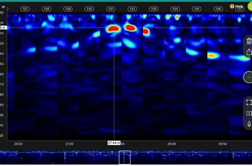
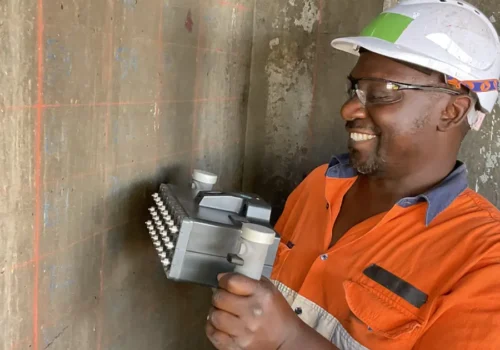
Other Applications of Ultrasonic Tomography (UT) imaging in the Concrete industry
- Voids and Air pockets in Concrete and Shotcrete
- Honeycombing and porosity in Concrete (may be due to poor workability, mix, poor vibration)
- Concrete segregation and non-uniformities in Concrete
- Non-homogeneity in Concrete as an indicator of non-uniformity of composition, density (due to poor vibration)
- Fracturing, Cracking and Concrete aging defects including:
- Intense fracturing and Deep crack propagation,
- Delamination failure (gradually progressing into Concrete spalling).
- Corrosion-induced stress cracking / delamination (progressing into Concrete spalling)
- Investigation of bonding integrity and strength at Cold-joints, presence (or absence) of inherent cast defects including honeycombing, voids (Air pockets), porosity, poorly bonded cold joints etc.
- Quality Checks (QA/QC) in Concrete repairs.
- Investigation of Water ingress in basements. Defect diagnosis of causation of failure in “confinement and compaction activated” Water barrier membrane over Shotcrete Basements.
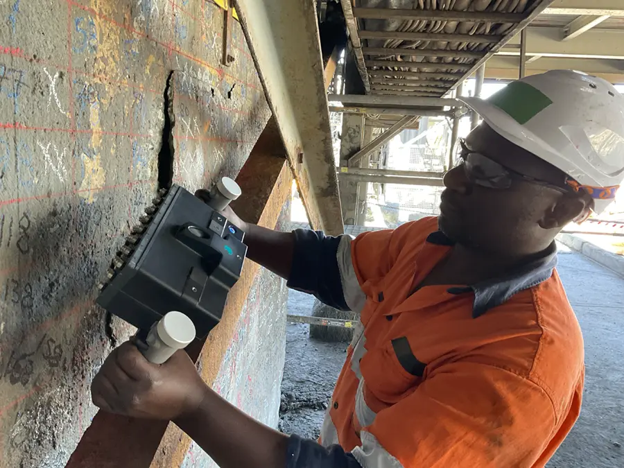
Why in some situations Ultrasonic Tomography (UT) imaging works better than GPR
Unlike Ultrasonics, GPR based technologies are electromagnetic in nature, suffer severe attenuation by increase in Conductivity (number of Steel reinforcement layers) and at worst, may be rendered ineffective in Steel Fibre reinforced Concrete that’s increasingly being used in most heavy-duty precast structures. Hence the versatility and efficiency of Ultrasonic technology.
3.1.1 Justification of method
The high-resolution Ultrasonic Tomography (UT) imaging offer multi-dimensional imaging options. The Ultrasonic Tomography (UT) imaging offers options including: [2D/3D], [B-scan, C-Scan, D-Scan can be produced to maximise anomaly illumination and resolution.
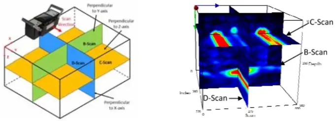
The views on the three orthogonal planes have formal names as shown in left figure above.
- C-scan shows the reflecting interfaces on a plane parallel to the test surface and at different depths (Z-axis); that is, it provides a “plan view” of the reflectors.
- B-scan provides an “end view” of the reflectors. The B- scan views are the same images created at each test location by the ultrasonic tomography imaging tool.
- The D-scan provides a side view of the reflectors.
The user can look at specific “slices” through 3-D model by defining the Z-coordinate for a C-scan image, the Y- coordinate for a B-scan image, and the X- coordinate for a D-scan image. Results are presented relevant to objectives and finely interpreted for further engineering assessment.