


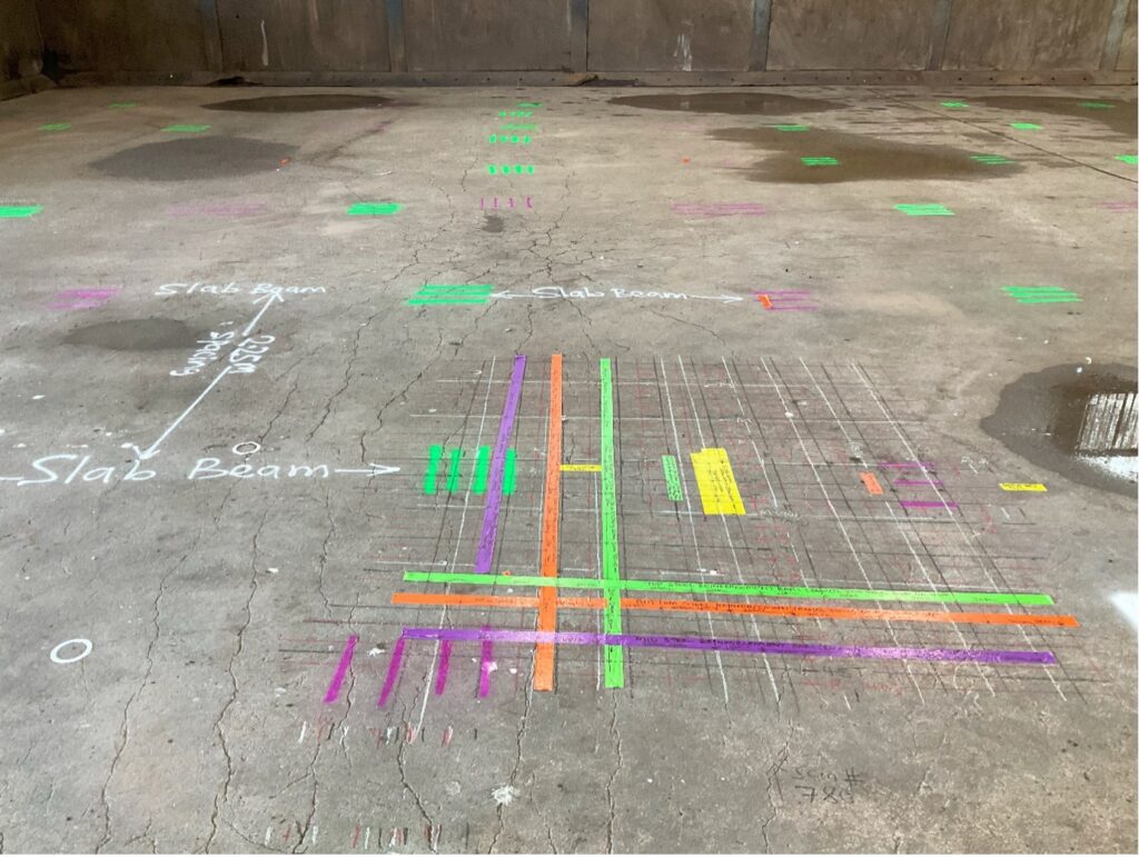
Scanning and Data collection
We’ve intentionally invested in range of state-of-the art high-resolution scanning, data processing and non-destructive testing (NDT) imaging technologies including Pulse radar (GPR based) Concrete scanners, Ultrasonic imaging technologies, Cover meter, Reinforcement sizing (Rebar diameter testing) equipment and specifically qualified and experienced personnel (Engineering Geophysicists and Structural Engineers) to deliver the most complex As-built structural verification / defects assessment and Structural auditing projects in a wide range of sectors including Public infrastructure (bridges, tunnels), Railway infrastructure, industrial and Marine structure.
Depending on the requirements, we deliver detailed and accurate outputs that are useable by architects and engineers to fully understand the As-built structural parameters (examples listed below), such are vital information that guides engineering / architectural design, loading assessments / capabilities and structural alterations.
Technology Standard: All aspects of Concrete scanning including data processing, interpretations of scans were done in accordance with ASTM D6432 – Standard Guide for Using the Surface Ground Penetrating Radar Method for Subsurface Investigation. In this case, the task was conducted using high-resolution 2D/3D Concrete scanning pulse radar imaging (GSSI Structural Mini XT 2.6GHz frequency).
As-built parameters from Scanning
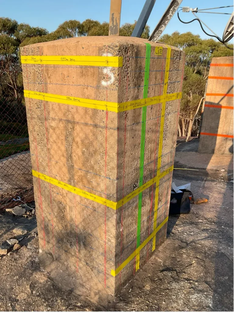
High-resolution scans are conducted in multiple axes and dimensions (longitudinal, transverse) for various structural elements including Concrete slabs, Beams, Columns, Footings, Walls, Bridges, Tunnels, industrial Concrete structures / heavy plinth footings to determine the following parameters :
- Dimensions (lateral, depth, thickness), Cross-section area,
- Concrete Cover to reinforcement in longitudinal and transverse axis, (top cover / Bottom cover)
- Primary and Secondary Reinforcement
- Steel reinforcement detail in longitudinal axis (top, mid, bottom / inner, mid, outer).
- Steel reinforcement detail in transverse axis (top, mid, bottom / inner, mid, outer).
- Spacing of reinforcement elements in longitudinal and transverse axes (top, mid, bottom / inner, mid, outer).
- Size and diameter of reinforcement elements in longitudinal and transverse axis,
- Type of Steel reinforcement elements (Ductility class N, E)
- Detail of Structural Beams (dimensions width x depth, detail (size, spacing) of reinforcement in longitudinal and transverse axis, (top cover / Bottom cover). Spacing of Beams
- Detail of Structural Columns (dimensions width x depth, detail (size, spacing) of reinforcement in longitudinal and transverse axis, (top cover / Bottom cover).
- Detail of Foundation Footings ( size/ dimensions width x depth, detail of reinforcement in longitudinal and transverse axis, (top cover / Bottom cover).
- Detailed of Masonry / Brick walls (Brick configuration, single / double walled/ triple-skinned, Reinforcement, Core-filled or not)
- In-situ Concrete Compressive Strength (MPa /KPa) testing either conducted non-destructively using Windsor probes, Rebound Schmidt Hammer averaging or the classic approach of extraction of Cores for laboratory compression testing.
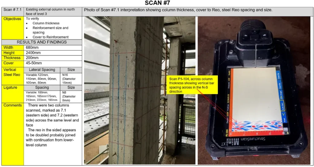
Detail of Structural Columns (dimensions width x depth, detail (size, spacing) of reinforcement in longitudinal and transverse axis, (top cover / Bottom cover).
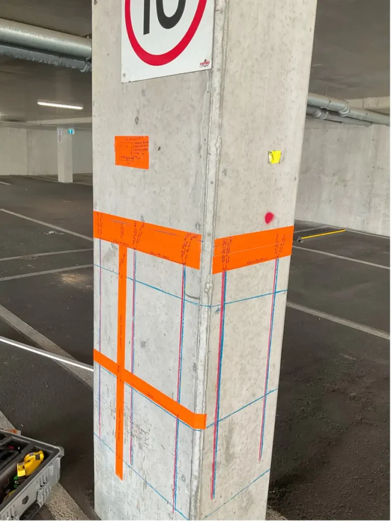
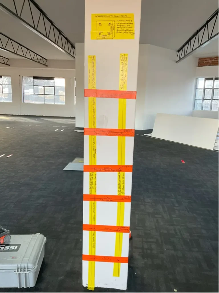
Detail of Structural Beams (dimensions width x depth, detail (size, spacing) of reinforcement in longitudinal and transverse axis, (top cover / Bottom cover). Spacing of Beams
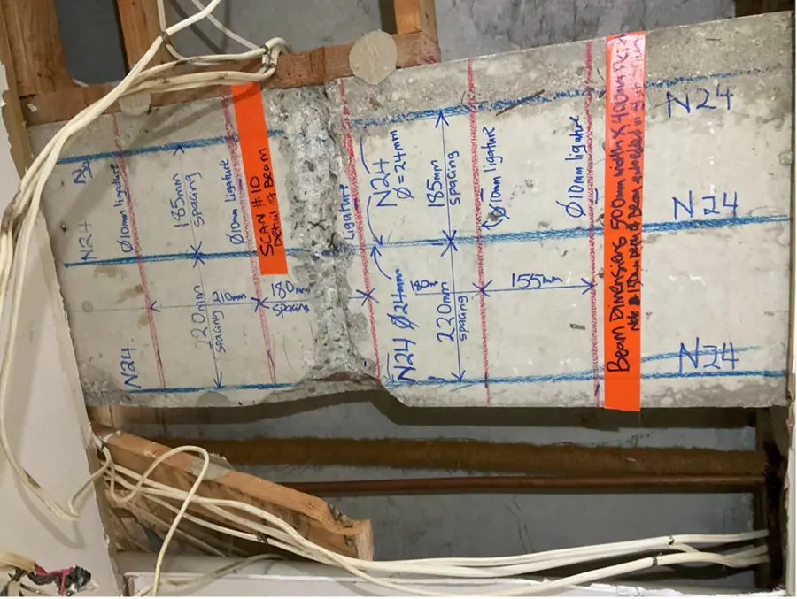
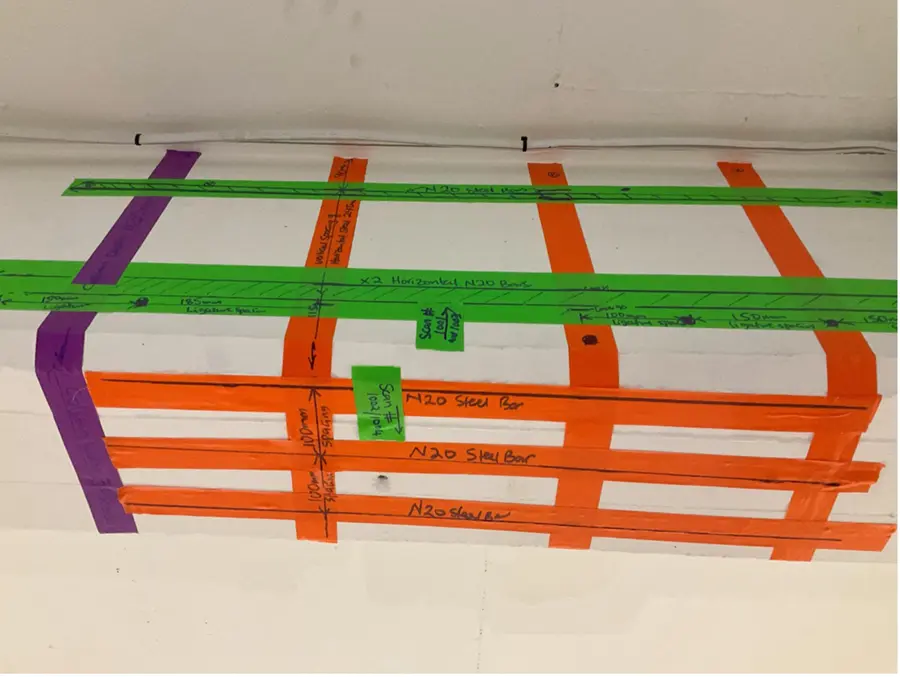
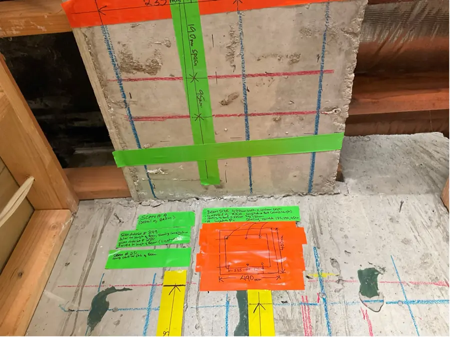
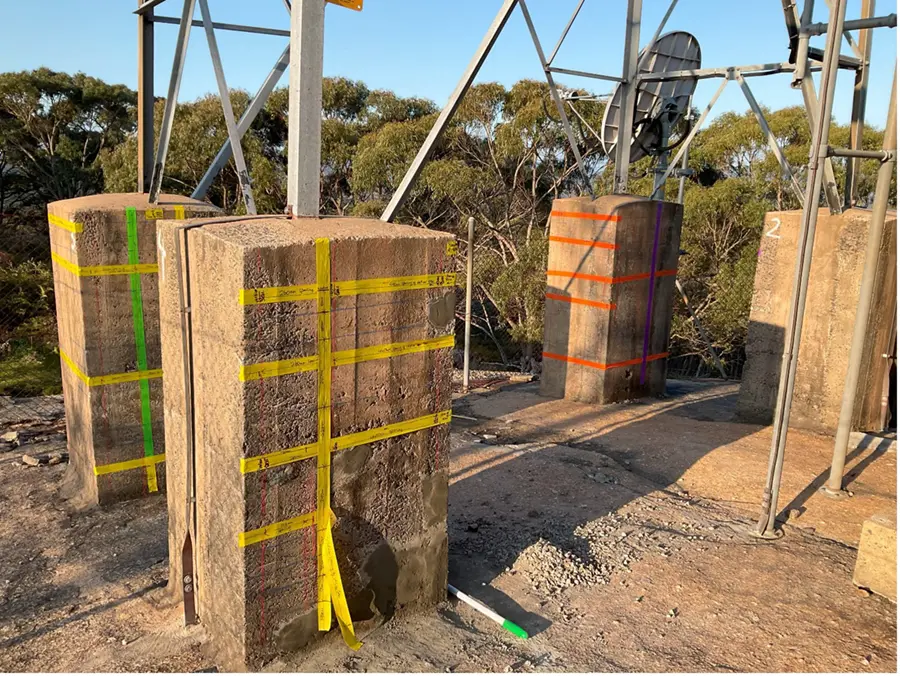
Detail of Foundation Footings (size/ dimensions width x depth, detail of reinforcement in longitudinal and transverse axis, (top cover / Bottom cover).
3.1.2 Data processing, Interpretation of Scan data
Reference to our standard method statement https://www.sigeoconcrete.com.au/ground-penetrating-radar-gpr-scanning/, data processing, interpretations of scans were done in accordance to ASTM D6432–19 Standard Guide for Using the Surface Ground Penetrating Radar Method for Subsurface Investigation.
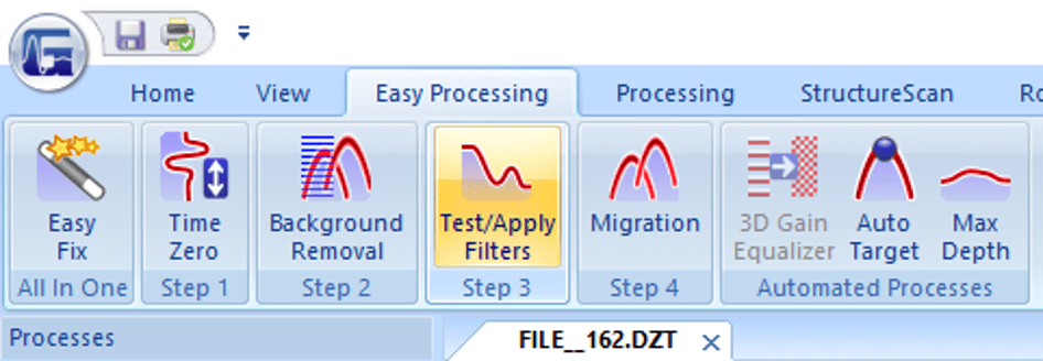
Below is a data processing flow sequence followed in data processing, GPR scan data, image resolution improvement, target migration and identification.
Safety & OHSE
Our approach prioritizes safety of all involved personnel, client’s assets, and the environment. Prior to commencement of work, Safe work method statements (SWMS) and specific task hazard assessments were assessed, discussed with personnel involved. Work was done in accordance to the SWMS and approach pre-established in the Job risk assessment.