

Scanning and Non-destructive Testing (NDT) of Shotcrete Structures e.g. Tunnels and Basements
With the wholistic goal of providing complete Shotcrete NDT testing solutions, we have intentionally invested in range of state-of-the art high-resolution scanning, data processing algorithms and non-destructive testing (NDT) imaging technologies including Pulse radar (GPR based) Shotcrete scanners, Ultrasonic imaging technologies, Cover meter, bond strength testing, in-situ Strength testing (for Concrete, Brick and Mortar), Reinforcement sizing (Rebar diameter testing) equipment and specifically qualified and experienced personnel (Engineering Geophysicists and Structural Engineers) to deliver the most complex As-built structural verification / defects assessment and Structural auditing projects in a wide range of infrastructure modern, heritage and ancient structures (including tunnels, bridge crossings, platforms and stations).
As-Built Structural Verification and Condition Assessment of ancient heritage categorised Railway Tunnels and infrastructure (Concrete, Masonry, Brick , Shotcrete).
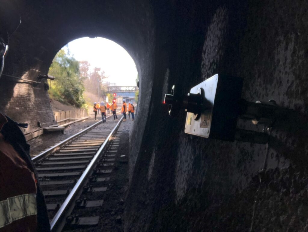
Depending on the requirements, we deliver detailed and accurate outputs that are useable by architects and engineers to fully understand the As-built structural parameters (examples listed below), such are vital information that guides engineering / architectural design, loading assessments / capabilities and structural alterations.
NDT Testing Methodology and Technology Standard
We provide a complete range of non-destructive (NDT) testing regime that includes the below enlisted techniques to in accordance with industry standards for testing Concrete, Masonray and Brick structures.
- Ultrasonic Tomography (UT) Imaging applied on Masonry using Proceq Pundit PD8050 in accordance to ASTM C1383, ACI 228.2R, ACI 437R standards
- Ultrasonic Pulse Velocity Testing (in accordance with ASTM C597 / BSI 98/105795 DC / ACI 228.2R Standard
- Windsor probe testing (in accordance with ASTM C-803 and ASTM C803/C803M-97C1 standard)
- Pull-off Test in accordance with ASTM C1583 standard.
- Sampling and Laboratory Testing of Materials
- Extraction of large diameter core samples in accordance with UIC 778-3R,
- Compressive strength testing of Shotcrete
- Scanning of Concrete and Masonry: All aspects of Concrete scanning including data processing, interpretations of scans were done in accordance with ASTM D6432 – Standard Guide for Using the Surface Ground Penetrating Radar Method for Subsurface Investigation. In this case, the task was conducted using high-resolution 2D/3D Concrete scanning pulse radar imaging (GSSI Structural Mini XT 2.6GHz frequency).
METHODS OF NON-DESTRUCTIVE TESTING (NDT) OF SHOTCRETE
Windsor Probe and Windsor Pin Testing of Strength of Shotcrete and Mortar (respectively)
For condition assessment / durability assessment of older brick / Concrete railway tunnels and modern Concrete, Shotcrete Railway infrastructure, we have a wide range of in-situ Strength (MPa / KPa) testing technologies including Windsor probes, Windsor pins, Rebound Schmidt hammers or depending on the consultant’s directives, we can extract core samples (where permissible) for laboratory compressive strength testing of Concrete and Masonry.
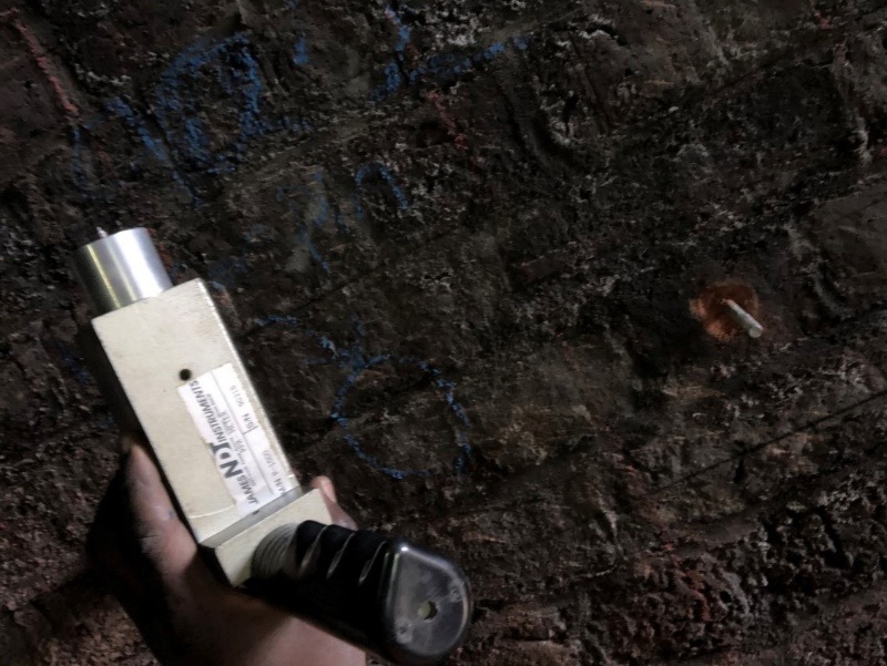
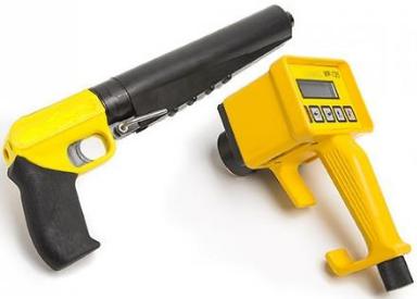
Photograph showing Windsor Pin probe instrument (Left) for measuring compressive strength of Masonry Mortar joints and Windsor Probe (For testing Strength of Shotcrete / Concrete)
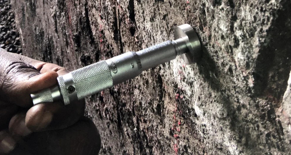
Figure Photograph showing Micrometre instrument for measuring penetration depth of Windsor pin into Masonry Mortar joints.
Ultrasonic Pulse Velocity (UPV) Testing
Ultrasonic Pulse Velocity Testing was conducted, and data acquired in accordance with industry standards ASTM C597 / BSI 98/105795 DC / ACI 228.2R Standard. The standard testing regimen, procedure was followed in all pre-data acquisition surface preparation, gridding, data processing and interpretation.
For verification of acceptability and use of the above ASTM standards in absence of Australian standards refer to: https://www.vicroads.vic.gov.au/-/media/files/technical-documents-new/technical-notes/technical-note-tn-061–nondestructive-testing-ndt-of-concrete-in-structures.ashx
UPV testing by the indirect method (as access to rear face is not available) involves sending ultrasonic waves through the brick and measuring their velocity, which is related to the stiffness and quality of the material. This can provide information on the integrity of the shotcrete and brickwork, including any internal voids, cracks, or deteriorated areas.
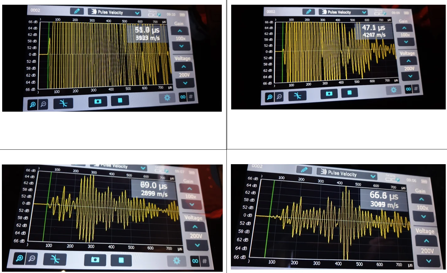
Below is an illustrational example of results presentation.
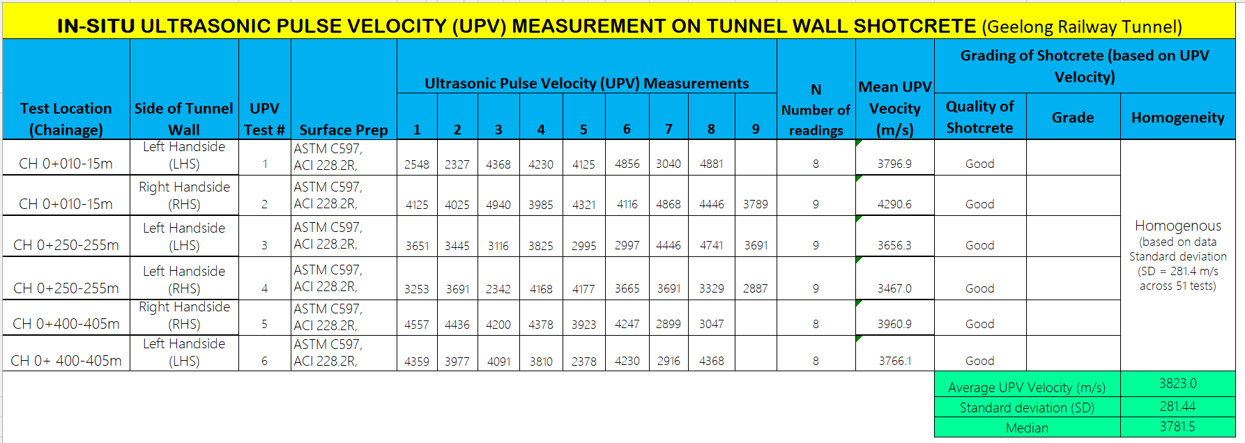
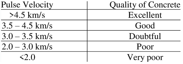
Grading and Homogeneity of Concrete industry established tabulated criteria for grading Concrete Quality, basing on Ultrasonic Pulse Velocity Measurements.
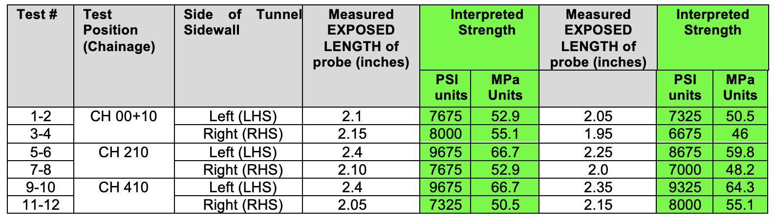
Interpreted Strength (in PSI and MPa units) from Windsor probe test measurements (based on Standard Power table)
Bond Strength Pull off testing of shotcrete
We can conduct pull-off tests, also known as a bond strength test or adhesion test, to evaluate the bond strength between shotcrete and its substrate (e.g., masonry wall) in accordance with ASTM C1583 – Standard Test Method for Tensile Strength of Concrete Surfaces and the Bond Strength or Tensile Strength of Concrete Repair and Overlay Materials by Direct Tension (Pull-off Method), using the Proceq DIY-216 pull-off tester.
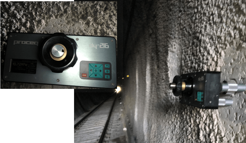
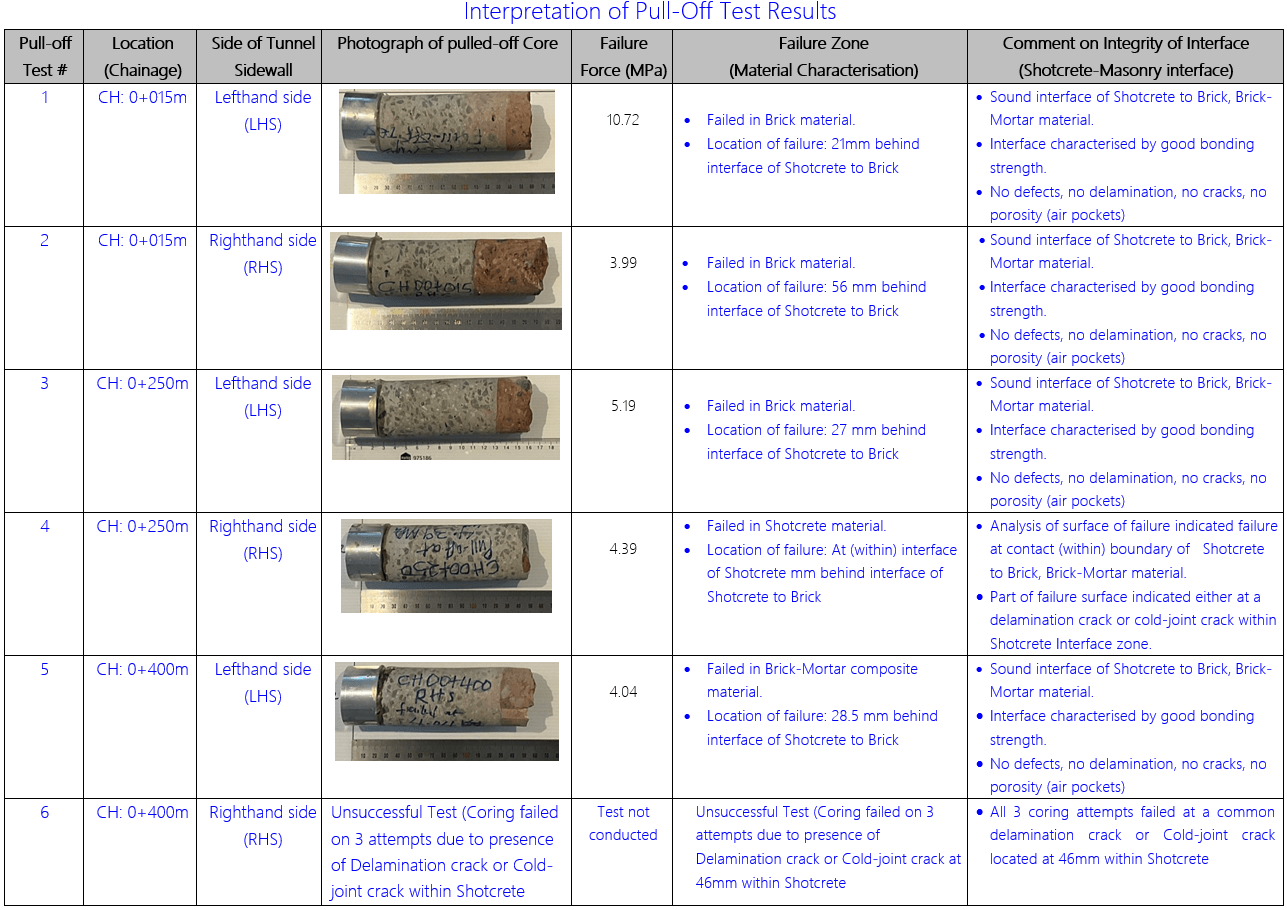
This test involves drilling of a core and then applying a tensile force to the shotcrete material to pull it off from the substrate, and measuring the maximum force required to cause bond failure. Below is an illustrational example of results presentation.
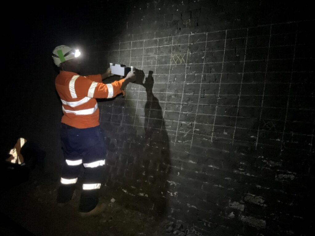
Ultrasonic tomography (UT) Testing of Masonry / Brick Railway Tunnels to evaluate integrity of Moisture barrier Membrane
6.2.1 Justification of method
The high-resolution Ultrasonic Tomography (UT) imaging offer multi-dimensional imaging options. The Ultrasonic Tomography (UT) imaging offers options including: [2D/3D], [B-scan, C-Scan, D-Scan can be produced to maximise anomaly illumination and resolution.
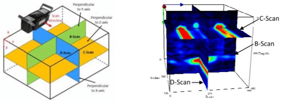
The views on the three orthogonal planes have formal names as shown in left figure above.
- C-scan shows the reflecting interfaces on a plane parallel to the test surface and at different depths (Z-axis); that is, it provides a “plan view” of the reflectors.
- B-scan provides an “end view” of the reflectors. The B- scan views are the same images created at each test location by the ultrasonic tomography imaging tool.
- The D-scan provides a side view of the reflectors.
The user can look at specific “slices” through 3-D model by defining the Z-coordinate for a C-scan image, the Y- coordinate for a B-scan image, and the X- coordinate for a D-scan image. Results are presented relevant to objectives and finely interpreted for further engineering assessment.
As-built parameters from Scanning
High-resolution scans are conducted in multiple axes and dimensions (longitudinal, transverse) for various structural elements including Concrete slabs, Beams, Columns, Footings, Walls, Bridges, Tunnels, industrial Concrete structures / heavy plinth footings to determine the following parameters :
Dimensions (lateral, depth, thickness), Cross-section area,
- Concrete Cover to reinforcement in longitudinal and transverse axis, (top cover / Bottom cover)
- Primary and Secondary Reinforcement
- Steel reinforcement detail in longitudinal axis (top, mid, bottom / inner, mid, outer).
- Steel reinforcement detail in transverse axis (top, mid, bottom / inner, mid, outer).
- Spacing of reinforcement elements in longitudinal and transverse axes (top, mid, bottom / inner, mid, outer).
- Size and diameter of reinforcement elements in longitudinal and transverse axis,
- Type of Steel reinforcement elements (Ductility class N, E)
- Detail of Structural Beams (dimensions width x depth, detail (size, spacing) of reinforcement in longitudinal and transverse axis, (top cover / Bottom cover). Spacing of Beams
- Detail of Structural Columns (dimensions width x depth, detail (size, spacing) of reinforcement in longitudinal and transverse axis, (top cover / Bottom cover).
- Detail of Foundation Footings ( size/ dimensions width x depth, detail of reinforcement in longitudinal and transverse axis, (top cover / Bottom cover).
- Detailed of Masonry / Brick walls (Brick configuration, single / double walled/ triple-skinned, Reinforcement, Core-filled or not)
- In-situ Concrete Compressive Strength (MPa /KPa) testing either conducted non-destructively using Windsor probes, Rebound Schmidt Hammer averaging or the classic approach of extraction of Cores for laboratory compression testing.
3.1.2 Data processing, Interpretation of Scan data
Scanning, data processing, interpretations of scans were done in accordance to ASTM D6432–19 Standard Guide for Using the Surface Ground Penetrating Radar Method for Subsurface Investigation.
Below is a data processing flow sequence followed in data processing, GPR scan data, image resolution improvement, target migration and identification.