
Parallel Seismic is a borehole test method developed for the determination of unknown depth deep of foundation elements and establishing the Toe-of-pile of the footing for structures including Telecommunication towers, Lighting towers, Bridge Pier foundations, Bridge Abutments, Railway Bridges, Marine piers and heavy industrial plinth footings for mining plant. It can also detect major anomalies within a foundation as well as provide the surrounding soil velocity profile information.
The depth of the foundation is determined by plotting the first arrival times as a function of depth and observing the depth where a change of slope occurs. This indicates the Toe-of-pile where the Concrete pile sits into the surrounding lithological earth material.
Alternatively, the foundation depth can be determined by observing the depth where the signal amplitude of the first arrival energy is appreciably reduced.

Why Parallel Seismic
(not Sonic Echo methods)
Parallel seismic has one unique unrivaled application in determining depth of deep foundations where the foundation is buried, capped by (has) an existing superstructure as parallel seismic is not affected by signal from the super structure or when the foundation is too long and slender for traditional sonic echo techniques.
When there a superstructure or Concrete slab on top of foundations (piers / piles/ mass block footing) most Sonic echo based technologies including classic low-strain pile integrity testing (PIT) method, run into one major challenge (the difficulty of separating the true echo from toe-of-pile due to the up-going echo from the superstructure induced down-going-echo as they are close apart) which severely complicates interpretation and leads to errorneous results of depth determination. At best, efforts to resolve this complication deliver an ambiguous answer with two possible depths.
Accurate Data Interpretation
(better than ambiguities of Sonic Echo methods)
Interpretation of parallel seismic data,
The depth of the foundation is determined by plotting the first arrival times as a function of depth and observing the depth where a change of slope occurs. Alternatively, the foundation depth can be determined by observing the depth where the signal amplitude of the first arrival energy is appreciably reduced. Deliverables include accurate determination of Toe-of-pile and depth-extent of Concrete footing below the ground.
Calculations based on the above geometry and formulae below.
- 1D travel-time model with a kink at the toe:
- For receivers shallower than or equal to the toe:
- For receivers deeper than the toe:
- For receivers shallower than or equal to the toe:


Benefits
(Simplified Geophysical and Geotechnical Interpretation)
Results are presented in a simplified format relevant to engineering purpose. Outputs may include:
- Determining Depth extent of Foundation with proof of Toe-of-pile
- Verification of Lithological material the Toe-of-pile is founded in by inference of Lithology / Geology based on Velocities of Medium
- Location of Defect along the Foundation
Lithological Logging (ASTM D 2487 standard)
For all drilling projects, we provide professionally compiled lithological profile logs to Unified Soil Classification System ASTM D 2487 standard
APPLICATIONS OF PARALLEL SEISMIC
(Solve Deep Foundations)
Depth of Radio Antennas Footings
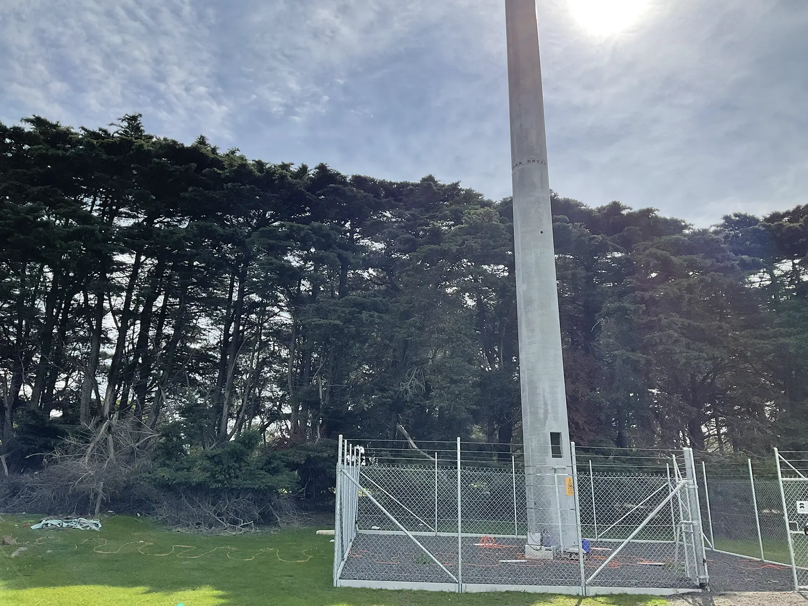
Depth of Lighting Tower Foundation Footings
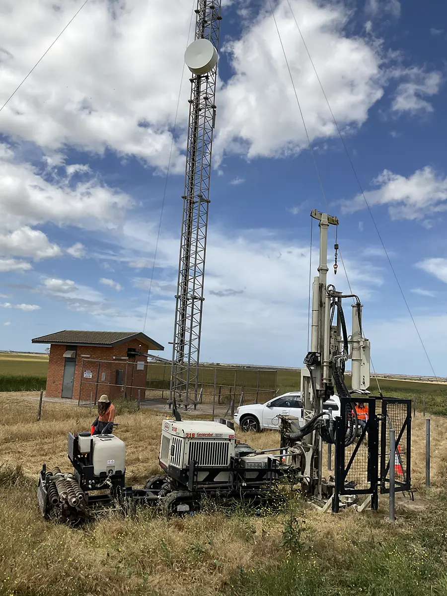
Depth of Telecom Tower Footings
METHOD AND APPROACH in accordance with industry standard ASTM D838
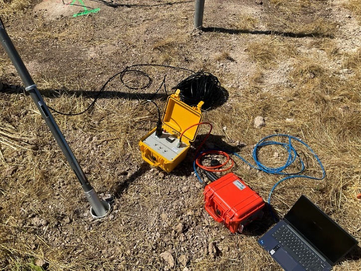
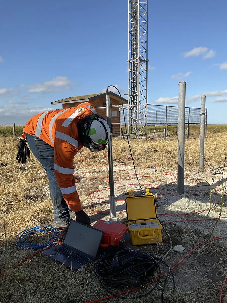
- Access Hole Drilling: A small-diameter borehole (typically 5 to 15 cm) is drilled as close as possible to the analysed foundation, extending well below the suspected foundation depth. This hole is typically lined with a PVC casing, anulus gap between soil wall preferably grouted or very thoroughly hydro-compacted to maximise coupling and filled with water.
- Sensor Deployment: A hydrophone (water-compatible acoustic receiver) is lowered into the borehole at regular depth increments.
- Seismic Impact: An instrumented hammer strikes an accessible part of the structure (or the foundation itself) to generate a seismic (compression) wave.
- Wave Tracking: The wave travels rapidly down through the high-density foundation material and also refracts into the lower-density surrounding soil.
Key Benefits
- Works on existing structures: Can test foundations even if the pile head is completely inaccessible or capped by a building or bridge.
- Material versatility: Highly effective on concrete, steel, timber, and masonry foundations.
- High accuracy: Typically provides foundation length estimates with high precision (approximately ± 5% margin of error).
- Deeper range: Has a much larger penetration range than standard sonic echo tests.
Limitations and Requirements
- Requires soil saturation: The soil surrounding the foundation and access tube must be saturated to allow for proper acoustic wave transmission.
- Site access: Requires space near the footing to drill an adjacent borehole.
- Complexity: Interpretation of results requires experienced geophysicists, especially in complex soil profiles or highly layered strata.